
If Your Belts are Misaligned, You are Likely Wasting Power and Money.
By Allen V. Reicks
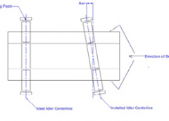
Figure 1 – Idler Angular Misalignment.
Have you ever driven your truck when the front wheels are out of alignment? Toe in or toe out makes you wander all over the road, your tires wear and if you are keeping track, reduces miles-per-gal. The same things happen on your belt conveyor, even if it seems to be running fine. Shiny rolls are a good hint that your idlers are fighting each other and wearing. Even if the belt tracks correctly, you are likely wasting power and money that can be saved with a one-time tune-up.
Aligning Your Idlers
Slots are provided in idler frames to allow easy adjustment of the idler angle. The hard part is knowing which way to adjust them. This is true for when idlers are first installed and most idlers are never moved after that. Sometime idlers are sighted in and then “knocked” to tracked the belt. At best, tape measures are used on the idler footpad to cross measure the frames. Both of these measures may incorrectly assume the frames were built precisely.
Part and assembly dimensional variations in the conveyor structure and idler frames accumulate quickly due to rough and worn fixtures, hole clearances, part warpage, and other manufacturing and installation imperfections. The best alignment is when the belt and rolls are used in the measurement but custom-build jigs necessary for this, until now, were only used on the largest conveyors. It is best to use the center roll because all of the rolls may not be in line and it carries most of the belt and bulk weight so it has the most influence on steering and power loss but it is the hardest to access.
Alignment measurement is a problem because the important features, the belt line and roll centerline, are not parallel or near each other. This prompted the development of a new Alignment Verification Rig (AVR), see Figure 2. This device uses magnets to quickly clamp to the idler roll and uses a rotatable laser to locate a plane perpendicular to the roll centerline. The angular misalignment can then be seen by comparing the laser plane location to two points along the belt edge. This allows fine tuning idler alignment after the belt is installed, even after many years, as long as the belt edge is reasonably unworn. Measuring to widely spaced locations on the belt inherently gives very good accuracy and indicates which way one footpad of the idler should be moved relative to the other. The same approach can be used in new construction if another laser or piano wire is used to indicate the belt line.
Calculating Power Lost and Power Cost
Let’s say you have a 36-in./C belt full of limestone aggregate and that your idlers average being ½-in. off alignment. That is, one side of the idler is ½-in. ahead of the other. Divide that by the width of the idler frame. Typically that’s belt width +9 in. or .5/(36+9)=.011 for the ratio of sideways movement to forward belt movement.

Figure 2 – Alignment Verification Rig (AVR) mounted to an idler and set to belt edge.

Figure 2a – Movement of the AVR laser for angular alignment to belt edge.

Figure 2b – Alignment target for improved accuracy.
Multiply by the load on the idler and a friction factor of .5 to convert to the sideways push at each idler (some push one way and some the other way). This force times the belt speed and operating hours is the energy lost. At 1600 tph and 600 fpm on a 300-ft. conveyor with a belt weight of 10 lb./ft., we get 3 hp or 2.2 kW wasted power. If you run 3,000 hours per year you are wasting $646 every year on this short conveyor compared to a more precise idler alignment of 1/16 in. This and the intangibles that go with it only costs a few hours from your maintenance crews. Longer and bigger belts save more.
To review: Cost of idler misalignment=idler misalignment/idler bolt spacing*friction factor*(conveyor tph*2000/60/belt speed + belt weight*2)* conveyor length in ft.* belt speed *.000023*hours per year*power cost $/kWhr. Or (1/2-1/16)/(36+9)*.5*(1600*2000/60/600+10*2) *600*300*.000023*3000*$.10=$646/year
(or, download a spreadsheet calculator.)
Idler alignment is identified as one of four main friction losses in CEMA’s belt book, 6th and 7th editions (see below). Misalignment design categories show average conveyor idlers have misalignments ranging from ¼ in to 1 ½ in. depending on the application. This range is wide because it may take more than a tape measure to get good alignment and the effect on the bottom line has been underestimated over the years. Bottom line, the more conveyor length you have, and the worse your idlers are aligned to the belt the more you can save, if you have a way to get very good alignment.
How Well are My Idlers Aligned? Why Does My Belt Track Fine?
Belt alignment is an important element of conveyor operation but is not the same as idler alignment. While idler angular misalignment can have a strong influence on belt lateral tracking, individual idlers typically counteract or fight one another.
The good news is that there is usually not enough side push on the belt to counteract the gravity centering in the trough and you get decent belt tracking. As a test measurement of your conveyor, measure the idler spacing on both stringers for a section of 10-20 idlers. Subtract the spacing of one side versus the other for each pair.
Some of the differences will be negative and some positive. If you average all of them, the result should be small if the belt is tracking well. If you drop all of the negative signs (absolute value) before averaging, the result will be larger and is an estimate of your sliding idler misalignment. See example in Table 1.
Table 1 – Example of Misalignment Estimate- 5 ft. spacing
This method does not include the variability in the frame assembly but only installation variation. The AVR can do this more accurately, quickly and easily from one side of the conveyor, both to assess the benefit to adjusting and to measure for future adjustment. Its low cost makes this a practical approach.
Background – Conveyor Power
Conveyor power usage has been a topic of interest ever since Thomas Robins started developing them in the 19th century. Conventional wisdom, supported by continuing measurement and research since then, understands that the power supplied by the conveyor drives is the sum of several almost independent categories. Individually or as a total, they can be compared by dividing by the weight of the belt and bulk load. The total friction can vary from .040 to .010 for the best conveyor designs.
Much of the world estimates the main resistances as “effective” overall friction, without the drag from pulleys, skirtboard etc. based on history. However, each category is affected by many material, design and construction details. The trade group CEMA has long recognized the individual impact of various parts and configurations and included a set of equations addressing each in its “Belt Conveyors for Bulk Materials,” including a significant refinement in the 6th edition in 2005 and later in the 7th edition. This approach has proven to provide much more information for design accuracy and optimization, especially since computers have allowed the many calculations and checks needed for thorough design over a wide range of cooperating conditions.
The main friction losses include:
- Belt rubber indentation rolling resistance from the hysteresis friction affected by temperature and compounding of the durable, filled rubbers used on conveyors.
- Idler alignment from imperfect angular alignment during manufacturing and installation.
- Idler rotating resistance from the design and manufacture including seal and temperature sensitive grease drag.
- Bulk material friction due to internal movement from belt sag between each pair of idlers, especially with belts with fabric carcasses and lower tension.
Inclines or declines dominate the power and belt tension when the slope is much greater than the arctangent of .04=2 degrees.
For long conveyors, these have a major impact on the capital costs due to the motor size, but more importantly due to the belt strength needed to overcome them and/or the number of idlers needed to control sag. The importance of each varies widely and is only known from detailed calculations and measurements. However, from an operating cost point of view, each impacts the energy cost. Other friction from pulleys, skirtboards and other accessories is important for short conveyors but also vary significantly.
A review of the CEMA-defined contributions for the friction losses or the “main” resistances, as they are called, for a range of conveyors indicate that each have a wide range of possible contributions to the total conveyor power, depending on many interacting design details.
- Belt Cover Indentation – 25 to 80 percent.
- Idler Rolling Resistance – 10 to 50 percent.
- Idler Misalignment – 10 to 60 percent.
- Material Trampling Movement from Belt Sag – 1 to 55 percent.
- Miscellaneous Component Friction – 2 to 10 percent.
More on Idler Alignment – Angular Installation Tolerance
As shown above in Figure 1, idler misalignment can have a significant impact on the motor power required to run a conveyor and the belt strength required to carry the tension. Idlers are misaligned in several ways, but this article concentrates on the angular installation variation. In an ideal conveyor system, all of the idler axes would all be perfectly perpendicular to the direction of belt travel, but a small error inevitably exists. The angular installation tolerance is a measure of how perpendicular the idler set is in relation to the belt travel direction or centerline of the belt.
Angular installation variation is the angle between the ideal centerline of the idler roll to the installed idler centerline (Aei in the diagram), but is generally measured at the idler mounting point, farthest away from the centerline of the belt. The Angular Installation Tolerance was introduced as an independent variable to be specified for new designs in the significant revision of the CEMA power calculation methodology in its 2005 6th edition.
Any angular misalignment increases the friction and power requirements on the conveyor system by introducing transverse slip between the idlers and the belt. This has been measured by the author to be a linear effect. The greater the angle from the ideal idler axis to the actual idler axis, the greater the transverse slip introduced. When the idler is not rolling in the exact same direction as the belt, an additional friction force is created and seen as an energy loss that the motor has to overcome. As more and more idler sets are misaligned along the length of the conveyor, more friction forces and losses are created and more power is required for running the conveyor.
Other misalignment types, specifically vertical and horizontal misalignment between idler sets, can negatively affect the conveyor in terms of idler loads and belt tracking, but they do not impact the required power like the angular misalignment is capable of. Forward tilting of the idler set, which are sometimes done intentionally to aid belt tracking, or the use of garland idlers can also have a significant negative impact on the required power for a conveyor.
While roll misalignment is also introduced when fabricating the idler frames, this should be a significantly smaller error if manufacturers use precise jigs. Different from the manufacturing of the idlers, idlers are installed on existing structure and tape measures are commonly used for alignment.
In many cases, during commissioning or with training idlers, the idler sets are slightly, but intentionally misaligned to help the belt track properly. The intentional misalignment uses the created additional friction forces from the transverse slip to push the belt along in the right direction. The need to intentionally misalign during commissioning may be a sign of poor idler or structure installation.
Calculating Angular Misalignment Losses
Accurately estimating the total friction for a conveyor is important so that the motor and belt are sized appropriately, and calculating the anticipated misalignment losses is an important part of the design.
Since each idler set can potentially be misaligned more or less than the previous one, the value used in the alignment loss calculations is the average absolute value of the misalignment of each idler set for the entire conveyor. CEMA states that angular installation will usually have an error of 3/8 in. to 1½ in., where the low range of misalignment typically applies to conveyors with permanent rigid structure where precise alignment procedures and tools may be used and the high range of misalignment are possible when moveable or roof-hung structure, or in other difficult installation environments.
The prediction of the friction forces created by the angular misalignment also requires the values for the belt width, belt weight, material weight, conveyor length and the sliding friction factor. The belt, material and length information are known during design, and the sliding friction factor has been measured to be 0.5 for steel idlers to rubber belting. Detailed calculations are provided in CEMA’s “Belt Conveyors for Bulk Materials” 6th and 7th Editions and used in modern conveyor design software such as Overland Conveyors Belt Analyst. Figure 3 shows the power breakdown from Belt Analyst for one example, though the size of the pie pieces varies depending on a range of design and installation details.
Conclusion
If idler alignment is planned for before construction, and then installed within the specification, conveyors operate at capacity and require less power to run, which allows the use of smaller motors and lighter belts, in addition to decreasing the initial and operating cost of the conveyor. Existing conveyors can often benefit from energy saving by realigning the idlers. The Idler Alignment Verification Rig (AVR) makes this process accurate and cost effective.
Allen V. Reicks. P.E., has spent much of his career at Overland Conveyor Co. and Precision Pulley and Idler (PPI). He is also the primary author of Chapter 6 Belt Tension and Power Engineering of the Conveyor Equipment Manufacturers Association (CEMA) “Belt Conveyors for Bulk Materials.” He can be contacted at avr4idlers.com.