

The drum motor belt drive design entered the conveyor industry in the early 1950s as a unique drive for belt conveyor applications, according to Alex Kanaris, president of VDG.
What sets the drum motor apart from a conventional conveyor drive is that the drum motor has all drive components, such as the electric motor, gear reducer and all bearings, housed inside the drum. Without exposed drive components and with no other drive parts rotating outside the conveyor frame, the drum motor presents a unique belt drive design. The drum motor also maximizes space utilization and worker safety, as components such external electric motor, gear reducer, bearings, chain and chain guards, all mounted outside the conveyor frame, are not needed. Those components can be hazardous to people required to work around conventional conveyor drives.
Most standard conventional conveyor drives use a 90-degree gear reducer mounted direct on the drive shaft or use sprockets and chain to drive the head conveyor drive drum. Using a 90-degree gear reducer, especially a worm gear reducer, impedes the efficiency of the drive, resulting in mechanical losses. In the drum motor conveyor drive, the motor is mechanically connected in-line with the gear reducer. This increases mechanical efficiency by 20-40%.
In short, a conveyor that uses a conventional drive system has all drive components that rotate the drive drum mounted externally. The drum motor drive uses no external drive components, resulting in a more streamlined conveyor design.
Design Overview
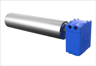
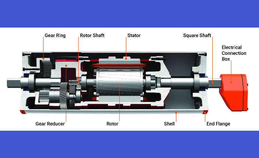
A drum motor has a cylinder with two square shafts on either side and an electrical connection box protruding on the side of the motor that houses the electrical connections. The shafts are square and do not rotate. They are fixed and mounted on the conveyor frame, eliminating the need for pillow block bearings. The electric motor that is housed inside the cylinder (drive drum) is an AC squirrel cage design motor. The stator does not rotate, therefore there is no need for rotating brushes or slip rings delivering power to the stator windings.
The rotor shaft is the input pinion driving either a two or three stage gear reducer. The last stage of the gear reducer is driving a gear ring that is bolted direct to the end-flange and the end-flange is bolted direct to the rotating drive drum.
All internal components, motor, gears, and bearings are working in an oil bath. The drum motor is hermetically sealed and one-third filled with oil. The oil inside the drum motor is used as a lubricant and also provides cooling. When the drum motor is running, the oil transfers the heat that is generated from the electric motor and gear reducer to the rotating drum and dissipated to the conveyor belt. As the temperature inside the drum motor rises, the internal pressure can rise up to 1 Atm (atmosphere) or 14.6 psi. Because of the internal pressure, it is necessary for the drum motor to be hermetically sealed to prevent oil leakage.
Range Of Drum Motors Belt Speed, HP and Drum Diameter
Depending on the manufacturer, drum motors are available in different drum diameters, belt speeds, and horsepower (HP). The diameter of the drum motor is dictated by the required horsepower and belt speed. Since all mechanical and electrical components have to fit inside the cylinder, the drum motor rating is geometrically restricted. In order to achieve the required belt speed, drum motors offer a range of fixed gear ratios. When a different belt speed is required it can be done by changing the ratio of the gear reducer or by using a frequency inverter. Drum motor diameters are available from 3.1- to 42.0-in. with a horsepower range from 0.25 hp to 500 hp.
Industries Using Drum Motors
Due to the self-contained design and the ability to withstand high pressure wash down procedures, the drum motor is a unique and attractive alternative to a conventional drive for the food processing industry. Industries using drum motors include warehousing, airport baggage systems, postal parcel, mining, aggregate, and other various belt conveyor applications.
Advantages and Disadvantages
Drum motors are more efficient than external mounted belt drives, resulting in lower energy consumption without any sacrifice in torque and performance. Drum motors contribute to a streamlined conveyor design and promotes workplace safety, because chain and sprockets are not required. The amount of time to install a drum motor into the conveyor frame is much less than the time required to install an external conventional drive.
The drum motor does not require any maintenance. However, in the event of electric motor or gear reducer failure, the drum motor has to be removed from the conveyor frame. Using the conventional external motor/gearbox drive system, repairs can be completed in less time because all drive components are located outside the conveyor frame and more accessible to maintenance personnel.
Market Penetration
In North America, the drum motor represents approximately 7% of the overall conveyor drive applications. With all the benefits that the drum motors offer, it would be reasonable to ask why the drum motor has such a low market penetration.
When drum motors first appeared in the market, the overall selection of belt speeds, horsepower, drum diameters, and drum lengths were very limited, with belt speed selection the larger issue. For these reasons, conveyor drives with chains and sprockets to power the head roller were more popular.
Changing belt speeds on conventional drives can be achieved by simply changing the drive sprockets. Changing the belt speed of the drum motor requires removing the drum motor from the conveyor frame and changing the gear ratio of the gear reducer. This problem has been largely eliminated with the introduction of variable frequency inverters. Adjusting the belt speed with a frequency inverter contributed to a relatively small increase in market penetration of the drum motor.
Market study indicates that conveyor manufacturers and end users implement the drum motor into their conveyor systems only when there are space constraints. Market feedback also showed issues with oil leakage, premature bearing, gear and electric motor failure. These drum motor issues had to be addressed in order to increase drum motor market share.
Drum Motor Design Issues and Solutions
Most drum motor manufacturers are producing drum motors as a sideline to other industrial products they manufacture or supply. Combined with low market penetration, these companies have little incentive to allocate funds and resources into research and development to improve the design in order to increase market share.
One exclusive drum motor manufacturer, with facilities in the United States, Canada and the Netherlands, invested in research and development to improve the drum motor design. In 2012, after an extensive study, the company developed the revolutionary designs of today’s drum motors.
The two-year study of testing and analysis revealed that lack of heat dissipation was a major issue impacting the overall product reliability. The basic principle of electric motor design is the method of cooling. The majority of electric motors used as conveyor drives are fan cooled, which is a very effective method of cooling an electric motor. Since all drive components of the drum motor are housed internally, fan cooling is not possible. Instead, the drum motor uses oil to transmit the heat from the electric motor to the drum shell and dissipates to the belt. Cooling of the drum motor through oil submersion is not as effective as the method of fan cooling of a standard conveyor motor.
Operating conditions can negatively impact the heat transfer from the motor to the belt. If for example an application requires the drum motor to have rubber lagging for belt traction, the rubber lagging will resist heat from exiting the drum motor. Stainless steel drum motors for sanitary and food processing applications are particularly sensitive to temperature elevations because stainless steel has poor heat transfer properties. Without sufficient heat dissipation, oil temperature rises, and the oil viscosity decreases and may not provide adequate lubrication, resulting in premature mechanical component failure. In addition, the elevated oil temperature increases the internal pressure which can affect the sealing system of the drum motor, and a potential for oil leaks.
In the past, all of these issues were mainly an inconvenience to end users but not a major detriment at the time, since belt conveyor engineers over designed and were liberal in selecting motor horsepower. More often, the specified horsepower of a drive would have been twice or more than the required horsepower needed to drive the belt conveyor. Due to this over design, conveyor drives, including drum motors, were not subjected to continuous full load conditions. Today, energy conservation is more important than any other time in our history. Conveyor equipment needs to operate longer hours, at full load and close to the rated drive performance. Equipment and drum motor manufacturers alike have been facing the same challenges.
In an electromechanical device such as a drum motor, there are two sources generating heat: the electric motor and the gearbox. The gear reducer counts for about 15% of the heat generation while the majority of the heat is produced by the electric motor. The electric motor also has two sources of heat generation: the current density of the stator winding, and the magnetic density of the laminated core.
By increasing these densities, the temperature generated by the electric motor will increase, and by reducing them, the temperature will decrease. However, reducing the current and magnetic densities in the electric motor to achieve lower temperature will also reduce the amount of work the motor will produce, resulting in a reduction of torque and horsepower. Therefore, the standard method of calculating electric motor windings is no longer valid and cannot be used to design the electric motor for drum motor applications.
Conclusion
The dedicated research and development conducted by the drum motor manufacturer resulted in a mandate for a new motor design that generates less heat inside the drum motor. This new motor design included using a new method of calculating the electric motor windings combined with different lamination sizes and materials with different metallurgic composition, has substantially reduced the drum motor temperature. Today, the new design drum motor offers an unmatched option for powering belt conveyors. As with most mechanical products, price, quality and reliability vary amongst the drum motor marketplace.
Ongoing investments in research and development by the drum motor manufacturer has developed a new intelligent drive. The intelligent design drum motor is capable of communicating with central plant control or other plant equipment. It is available in different gear configurations, from high to low belt speeds, 3.1-in. diameter to 42-in. diameter, and horsepower ratings from 0.25 hp to 500 hp.