
HOW TO SELECT THE BEST MOTORS AND MOTOR CONTROLS FOR MINING APPLICATIONS.
By Paul Blaiklock and William Horvath
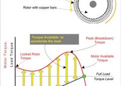
| Figure 1. Induction Motor Accelerating a Load from Stopped to Full Load. |
When determining how to optimize mining equipment for maximum efficiency, you first need to understand the different characteristics of motors, and how their behaviors can be modified with key motor control methods to best fit each type of application.
This article will review a variety of motors, the types of equipment that use those motors and how to select the best control system based on controlling motor speed and torque.
Basic AC Motors and Their Characteristics
Although DC Motors are still widely used in draglines and shovels, for the purpose of this article, only three-phase AC motors will be addressed.
These motors include:
- Induction motors.
- Synchronous motors.
- Utility fed motors, fixed speed.
- Motors fed by variable frequency drives – both VFD start only and variable speed types.
Induction Motors
In the induction motor cross section sketch of Figure 1, the stator has a three-phase AC winding to create a rotating magnetic field. The copper bars in the rotor act as shorted transformer secondary, and the current induces a rotor field flux, which produces torque.
The rotor voltage depends on the difference between the stator wave rpm and rotor mechanical rpm. This is called slip. If there is no slip then there is no power. The power factor is always lagging.
Starting Induction Motors
Induction motors connected across the line at start draw large currents, approximately 600 percent of rated current, and this current remains high through most of the start.
The curves in Figure 1 show a standard induction motor starting directly across the line driving a variable torque load such as a pump.
The red curve shows the motor available torque, and the torque needed by the load is shown in black. The difference between the available and required torque, the yellow arrows, represents torque to accelerate the load to the next speed point.
Induction Motor Behavior with a Variable Frequency Drive (VFD)
Starting the motor with a variable frequency drive, like TMEIC’s TMdrive-MVe2, provides many advantages besides variable speed. The VFD voltage and frequency are both adjusted very accurately – to match the process needs. High starting currents and stresses are eliminated, so there is no “starts per hour” limit. The utility current starting surge is eliminated and power factor is good over whole speed range. The motor can be controlled to make rated torque (or more) over the whole speed range.
 |
| Figure 2. Synchronous Motor Starting Curves before Synchronization. |
Synchronous Motors
The rotor of the synchronous motor in Figure 2 has six-poles with field windings normally fed by DC current from an exciter. DC power can come in through slip rings or be generated by a brushless exciter on the shaft. Three-phase AC power on the stator sets up a rotating field magnetic flux.
For starting, the rotor Amortisseur acts as shorted transformer secondary, and the current produces rotor flux like an induction motor.
The torque produced accelerates the load to near synchronous speed. During starting, the DC field poles are shorted by a discharge resistor. At near synchronous speed, the DC field is applied and the rotor synchronizes to the line.
Pull-In Torque (Not applicable to VFD control) is the maximum connected load torque under which the motor will pull its connected inertia load into synchronism, at rated voltage, frequency and with rated field applied.
Pull-In speed (Not applicable to VFD control) is the speed at which a motor will bring its load into synchronism – dependent on the inertia of the revolving parts and the load torque.
Pull-Out Torque is the maximum sustained torque, which the motor will develop at synchronous speed without stepping out, with rated voltage applied, at rated frequency and excitation.
Some notes on Synchronous Motor Starting:
- Speed of 95-97 percent is a typical field application point.
- “Best Angle” field application may not be needed – timed application is often effective and simpler.
- Turning on current to the field coils too soon can create excessive torques when locking in to synchronous speed.
- Open circuit fields during start create high voltages (10,000 volts or more), so there can be damage to fields and slip rings. Either a short circuit, diode rectifier, or a resistor should be used across fields during start. Using an optimal resistor can give 30-50 percent more start torque. Voltage surge protectors are used across slip-ring type fields.
- Field application contactors connect the DC before the discharge path breaks.
- Synchronous motors are stressed by starting; the design limit is two cold starts per hour, full voltage 600 percent inrush amps, at 15-20 percent pf is typical.
Synchronous Motors Fed by VFDs
The VFD provides variable speed operation and easy starting. Very large synchronous motors can be started unloaded with a VFD, brought up to synchronous speed and then synchronized to the utility. In installations with multiple motors and appropriate switch gear, the VFD can sequentially start all the motors.
Starting the motor with a variable frequency drive:
- The field is energized first, with an AC exciter or slip ring DC power; the motor is synchronous with the VFD as it starts to turn, this allows for very high starting torque.
- The system must know the rotor position using an absolute encoder, or by finding the rotor position by calculation
- Amortisseur bars (dampening windings) are important for impact or erratic loads
- Motor starting characteristics are not utilized
- The motor may be transferred to the utility by switchgear when volts, frequency, and phase match
For variable speed operation, the motor speed is controlled by the frequency supplied to the stator. Constant Volts per Hertz is applied by the VFD control system to maintain constant flux. It is possible to run the motor at high frequencies above 60 Hz to obtain high RPM if the motor is designed for this speed; this is known as “super-synchronous” operation.
The control system changes the field current based on load to maintain unity Power Factor (minimum current). As in a fixed speed application, any load change creates a load angle change and instantaneous speed change. Note that zero speed (near DC) is difficult for drive power devices.
Motor Starting Without a VFD
Less expensive starting devices, which reduce the voltage to the motor and the current, are available. They have a bypass contactor, which closes after a time delay for acceleration. They include:
- A reactor – places impedance between the motor and power source.
- An autotransformer – is more effective than a reactor as it transforms and decreases the line current while setting motor current.
- A reactor-capacitor starter – cancels the voltage drop from bad motor starting power factor.
- A solid state starter – can limit the current, and accelerate the motor for a preset time.
Unlike a VFD, these reduced voltage-starting devices apply full utility frequency to the motor.
Comparing Induction and Synchronous Motors
Both types of motor are similar in that they follow the stator rotating 3-phase magnetic flux wave, and the RPM is dependent on the frequency of the source. There are many differences as summarized below.
 |
| Figure 3. Wound Rotor showing Slip Rings. |
Wound Rotor Motors
A Wound Rotor Induction Motor (WRIM) is a special induction machine with a three-phase wound stator, and the rotor also has a three-phase winding, usually connected in a wye (or star) circuit. The three terminals of the rotor winding are connected to separate slip rings, which are normally connected to a variable resistance such as a liquid rheostat or resistor bank, which is used for starting the motor.
The speed of this motor can be adjusted by changing the rotor resistance, which affects the slip, rotor current, torque and the speed. In addition to variable speed, the starting torque and inrush current can also be controlled.
When up to operating speed the slip rings can be shorted and the WRM acts like a conventional induction motor.
In older systems the power in the resistor can be lost as heat. Later, speed control of wound rotor motors employed slip power recovery (SPR) controls for cost and energy efficiency reasons. These older implementations of SPR technology saved energy, but have disadvantages of low power factor operation and torque pulsations.
The use of low-voltage pulse width modulated converters to collect the slip current eliminates these disadvantages while retaining all the energy savings, and is appropriate for new or existing motors.
Key Motor Control Methods
Now that we’ve identified the several different types of motors and their characteristics related to speed and torque, lets discuss how to augment them based on some common control methods.
Controlling Speed. Some machines work well at fixed speeds, such as mining conveyors, crushers and draglines. Control for these motors is focused on reliable, safe starting.
Other equipment, like pumps, and centrifugal compressors, can benefit from variable speed. Control for these motors is focused on determining optimum speed setting.
Controlling Torque. In addition to controlling speed, you also have to consider torque requirements. Mine machinery torque profiles are all over the map – some wildly swinging, some smoothly predictable. Torque control focuses on providing adequate torque for the load at all operating points, and on protecting the equipment and people from excess torques and currents. Motor torque and motor current are roughly proportional.
For equipment protection, the motor control must work within limits:
- Driven equipment mechanical limits such as couplings, gearboxes, pressures, and speeds.
- Driven equipment electrical limits such as voltages, currents, and frequencies.
- Process limits such as temperatures, flows, and material feed.
Power system effects and limits must be recognized, including the available system voltage limits, the actual voltages available after system voltage drop and current harmonic distortion.
The motor control unit must feed voltage, frequency, and current to the connected motor to produce the required speeds and torques.
In addition, the control must:
- Recognize and work with the actual motor torque, voltage and current characteristics.
- Protect motors from damaging currents and voltages
Generally the motor can generate torque as shown in the curve of Figure 2. The physical load type and the equipment determine the torque-speed characteristic, while the level is set by the actual conditions such as moving loads uphill or downhill. Load torque varies with operating speed in different ways; the two main types of load are Constant Torque and Variable Torque.
 |
| Figure 4. Motor, Motor Control, and Mining Load |
Mining Loads and Their Categories
The main motor applications in the mining industry are constant torque shown in Figure 5. They are segregated by constant torque, variable torque, and a third type, which has both characteristics
Variable Torque Loads. Variable torque loads include pumps, fans, and centrifugal compressors, as mentioned earlier. In these applications the flow rate varies proportionally with the speed, and the pressure and load torque varies as the square of the speed. Since motor shaft power is the product of torque and speed, the shaft horsepower varies as the cube of the speed.
In-Between Torque Loads. Loads “In-between” have both constant torque and variable torque characteristics. Examples are pump loads with entrained solids such as slurry pumps, and fan loads with heavy concentrations of dust or solids such as cyclones and separators.
Constant Torque Loads. With constant torque loads, the torque loading is not a function of speed. As the speed changes, the load torque remains constant and the horsepower changes linearly with speed. Constant torque loads cause motors to draw relatively high current at low speeds when compared to variable torque applications
 |
| Figure 5. Types of Mining Loads by Torque Requirements. |
Equipment Requiring Constant Torque
Mining Conveyors. Mining conveyors exhibit fairly constant torque over their normal operating speed. The application issues include starting torque and protection of the belt from over-torque. Also the belt tension changes when there are wide weather changes, and when the material weight changes.
With a long conveyor, starting or breakaway torque is high, but once moving the torque is fairly constant. In the case of a downhill conveyor at higher speeds, there can be the opportunity to regenerate power back to the supply.
Crushers. Crushers, which break the materials into a more uniform particle size for processing, are another example of a constant torque load application. Characteristically crushers have high peak torques, and the potential for jamming. In many applications they are used with controlled speed feed conveyors.
Grinding Mill Types and Operation. Three main types of grinding mill are used. In the Autogenous mill ore is broken up by collisions with itself, and in the Ball mill, by collisions with steel balls. The Semi-Autogenous (SAG) mill uses a mixture of both the ore and balls. Once started, the mill torque is fairly constant.
Draglines and Shovels. Dragline loads are “constant torque” type, but loads vary widely and often wildly. There are four load quadrants including two quadrants for motoring, and two quadrants for regeneration. Since there are four-quadrants; they require responsive controls.
Electric Blast Hole Drills. Electrically driven drills for blasting operations have three motions, drill rotary, propel, and pull down. Peak torque can be high, for example initiating the drill-unscrewing mode, which requires reverse direction high torque for breaking loose the drill stem.
Putting It All Together
As discussed, a wide range of different mining machinery is in use for different processes. Each application has its own unique torque speed requirements, which are met with different motors and different starting devices.
To review, the different types of applications can be divided into Constant Torque Loads, Variable Torque Loads, and loads with some of both.
There are three types of motors available for these applications, Induction, Synchronous, and Wound Rotor Motors, along with a selection of starting devices, some of which provide the capability for changing the operating speed.
So how do you choose the right type of motor?
When considering an Induction Motor or Synchronous Motor you can start by evaluating your needs, and carefully selecting the right motors and drives for your operation will maximize your efficiency and increase your overall output.
Paul Blaiklock is marketing manager, and Bill Horvath is a senior application engineer for TMEIC in Roanoke, Va.