
A Cost-Effective Method Of Sealing Slurry Pumps, Whether Centrifugal Or Dynamic Expeller Seals.
By Will Pierce
Dynamically, or centrifugally, sealed pumps have been around industry for more than 100 years. The original design was patented in the early 20th century and, after the patent expired, pump companies all over the world expounded upon this then-novel shaft seal design. The seal has been called various names by various manufacturers over the years, e.g. expeller seal, dynamic seal, centrifugal seal, dry-gland, among others.
The Schurco Slurry expeller seal has its roots in this design, but with significant enhancements over the years with an eye toward wear reduction in slurry pumping. This seal maintains relevance in industry today, even after 100 years on the market, due to its relatively low cost of implementation, and its ability to eliminate the need for clean flush water as is required for standard packed gland/stuffing box pumps.
In handling difficult slurries, the process can frequently be improved by eliminating the need for seal water in the stuffing box. In the production of water-soluble potash, for example, any additional water introduced in the course of processing the ore must eventually be removed, raising the cost of the already expensive compound. Clean water can often be hard to come by in mining mills and mineral processing environments, and packing and sleeves may fail quickly when abrasive particles in the seal water or slurry itself enter the stuffing box.
Operating Principles
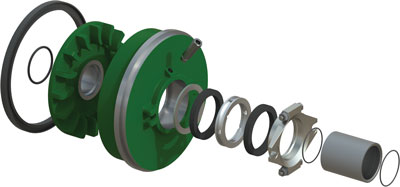
The physics governing expeller operation are straightforward. As the expeller rotates within a confined cavity, the vanes impart forces to the mixture of fluid and solids within the cavity, causing it to rotate about the shaft in a manner similar to a forced vortex. Centrifugal action associated with this rotation causes the mixture to move outward, away from the axis/shaft. The expeller housing, also called an expeller ring, confines the outward motion, and directs the slurry away and out of the cavity.
The net result of the is action is the creation of a low-pressure area about the shaft. Air fills the region of low pressure, and a concentric mixture-gas interface is formed at some indeterminate radial diameter within the expeller vanes. The interface is essential as it forms a distinct barrier between the mixture and the shaft. It also protects the static seal within the bore of the packed expeller ring from exposure to abrasives during pump operation.
Static Seal
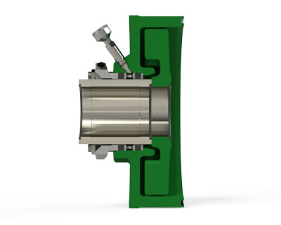
Since it is not feasible to drain pump boxes (sumps) for every shutdown of a slurry pump, the shaft seal must be made to function when it is not operating as well as when it is operating. The centrifugal forces as described above act to create a seal around the shaft during pump operation; however, when the pump is not operating, those same forces are not present. Instead, static elements within the expeller ring must be incorporated to seal the pump against the static column of water or mixture left in the tank feeding the pump or flowing back from a pipeline that has ceased flow in the downstream direction.
This can be accomplished via two common means:
- Grease lubricated packing (see Figure 2).
- Static lip seals (more common with elastomeric expeller rings).
The grease must be replenished regularly to maintain the static seal in option one above. The lip seals employed in option two can wear into softer shaft sleeve material, but with proper sleeve material selection, e.g. using a hard-coated shaft sleeve, the static lip seals can provide long lasting service.
Application
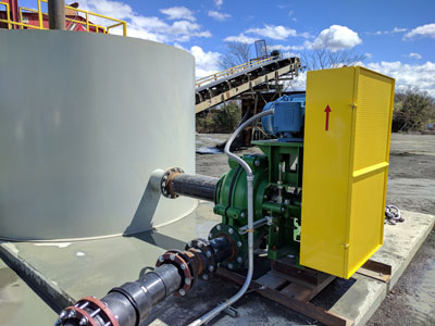
Expellers can be applied in virtually all slurries regardless of solid concentration. Slurry pumps, such as the ones that Schurco Slurry manufactures, are uniquely suited for expeller seals due to the abrasive nature of the slurry being pumped, and the typical lack of readily available, clean and pressurized gland seal water.
Slurry pump impellers general have protruding vane-like surfaces on the back-shroud (and front-shroud as well, in the case of closed face impellers) as seen in Figure 3.
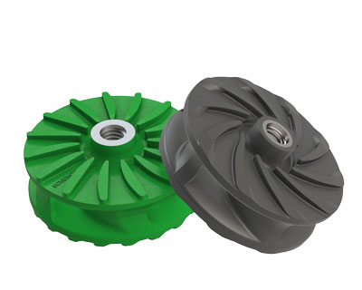
These pump-out or expelling vanes serve a purpose beyond just removing solids that may happen to slip between the faces of the impeller shrouds and the front and back of the pump casing or liners.
The expelling vanes on the back shroud of the impeller also aid in reducing the pressure within the expeller ring cavity, thereby increasing the effectiveness of the expeller’s ability to generate the fluid/vapor barrier between the shaft and expeller vanes. Pumps without these expelling vanes will suffer from decreased expeller efficacy.
There are many expelling vane designs that have been trialed by various manufacturers over the decades. One design, which was pioneered in the mid-1990s, is hockey-stick style expelling vanes. They are very effective at reducing pressure in the expeller ring cavity; however, can be prone to clogging with sufficiently large or sticky particulate. The most common design, which strikes a balance between expeller ring cavity pressure reduction, particulate expulsion, and extended wear life is the radial vane design as seen on the green (left) impeller shown in Figure 3.
General Rule of Applicability
The amount of suction intake head that can be tolerated by a centrifugal seal before it leaks is limited by several factors.
- Density of Slurry – The differential pressure between the expeller seal and the impeller main pumping vanes increases as the density of the slurry being pumped increases. This happens because the density of the fluid in the expeller chamber is less than that of the slurry being pumped. This is a result of a portion of the solids being centrifuged out of the confined space in the expeller ring area. The pressure developed is proportional to the density of the slurry. Consequently, the pressure developed by the expeller and impeller back vanes on low density slurry can become less than the pressure developed by the impeller pumping vanes on the high-density slurry.
- Head Flow Characteristic (Pump Performance Curve) – The centrifugal seal can tolerate higher suction heads if the pump has a steep pump performance curve.
Expeller Seal Suitability
Through decades of testing and field experience, some general rules for the application of expeller seals have been developed. While not foolproof, they apply for most applications.
There are two head factors to be considered when applying an expeller seal:
- Sealing head responsible for successful centrifugal sealing = combined head developed by the impeller’s expelling back shroud pump-out vanes and the expeller = pump shutoff head (approximately).
- Pump discharge head = head developed by the pump (total dynamic head [TDH]) + suction head.
One must be greater than two to avoid seal leakage. This heuristic shows that steeper pump performance curves have better expeller sealing characteristics than flatter pump performance curves. Additionally, operation closer to the Best Efficiency Point (BEP) on a pump performance curve will lend itself to a greater tolerance of higher inlet pressures.
When in doubt, contact the factory for a final determination of the appropriateness of an expeller seal for any given application. Design improvements and additional field data drive innovations and changes to recommendations, which may or may not be published.
Expeller Incompatible Operating Conditions
Expeller seals are offered whenever possible; however, the following conditions of service require the use of alternative sealing means:
- Multi-stage or series pump duties.
- A pump operating with high positive intake head (generally higher than 15 ft. [4.5 meters]).
- Suction lift duties – air may be drawn in through the seal chamber causing the pump to lose prime.
Power Considerations
An important factor to consider when specifying or using an expeller seal in a centrifugal pump is the power that is consumed by the seal, taking away from the overall hydraulic efficiency of the pumping unit.
This efficiency derating factor can be conservatively estimated at a 3% loss of overall published pump efficiency at any given duty point. Specific application considerations should consult with the factory for suitability.
Conclusion
Expellers carry significant advantages over comparable shaft sealing methods in slurry pumps:
- Either no seal water is required, or a reduced amount may be required due to the reduction of pressure in the expeller ring cavity.
- Slurry is not diluted by seal water.
- No gland leakage when properly applied, lubricated and maintained.
- Maintenance of the packing and shaft sleeve are significantly reduced due to the reduction to near zero of slurry and pumpage in and around the shaft seal area.
Where expellers are found unsuitable, packed stuffing box seals may supplant the expeller for the application providing that there is sufficient clean and adequately pressurized gland seal water available to flush the seal.
Finally, mechanical seals may provide a desirable alternative; however, they carry the greatest capital cost, and can incur the highest operating and maintenance cost should site conditions not be favorable to mechanical seal use and care.
Schurco Slurry promotes the application and use of expeller seals wherever possible or accepted due to their low capital and ongoing operating and maintenance cost when compared to packed gland or mechanical seal alternatives.
Will Pierce is vice president of engineering, Schurco Slurry.